Trace Editor
| Line 58: | Line 58: | ||
**'''Show Soma:''' If Loaded will display segmented soma. | **'''Show Soma:''' If Loaded will display segmented soma. | ||
| − | + | ==Complex Edit Operations== | |
Note that the functions listed above are designed to handle multiple segments at a time. The MinEndPoints function determines the closest distances between trace endpoints, distances greater than the threshold are rejected. For detailed information on the features used in computation please see [[Trace Editor/Features]]. Conflicts between two lines attempting to connect to one endpoint are resolved by finding the closest endpoints. The merge command can be invoked on a set of traces, and this function will automatically connect all the possible segments. Multiple tracelines can be orginized and merged into a single linear trace. | Note that the functions listed above are designed to handle multiple segments at a time. The MinEndPoints function determines the closest distances between trace endpoints, distances greater than the threshold are rejected. For detailed information on the features used in computation please see [[Trace Editor/Features]]. Conflicts between two lines attempting to connect to one endpoint are resolved by finding the closest endpoints. The merge command can be invoked on a set of traces, and this function will automatically connect all the possible segments. Multiple tracelines can be orginized and merged into a single linear trace. | ||
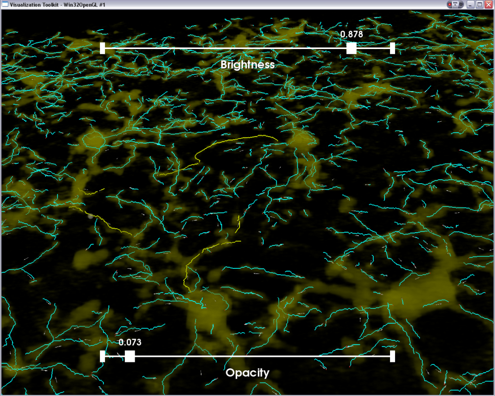
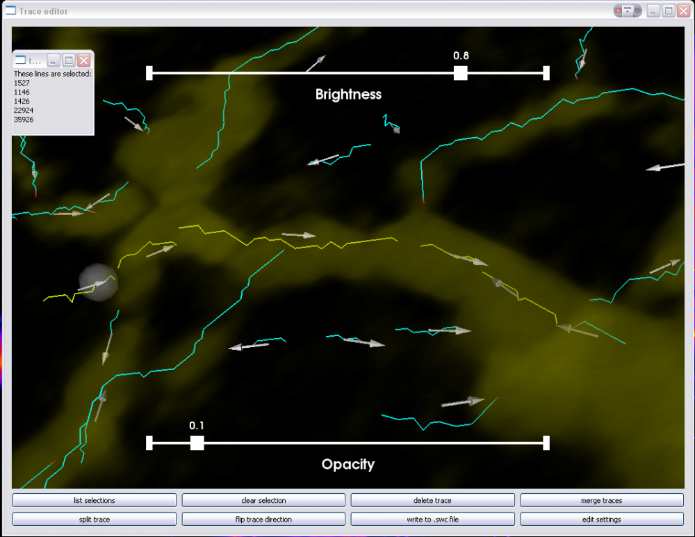
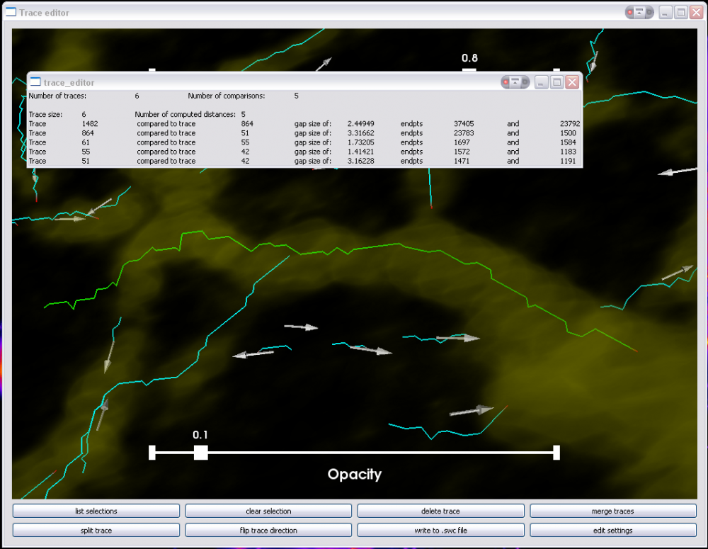
[[Image:GuiMerge1.png|thumb|1000px|'''Illustrating the process of merging trace segments:''' The user has selected a set of trace segments to be merged. These are highlighted in yellow. By clicking the List button, or pressing 'l' on the keyboard, a popup window is created to list all selected lines.|center]] | [[Image:GuiMerge1.png|thumb|1000px|'''Illustrating the process of merging trace segments:''' The user has selected a set of trace segments to be merged. These are highlighted in yellow. By clicking the List button, or pressing 'l' on the keyboard, a popup window is created to list all selected lines.|center]] | ||
Revision as of 20:14, 2 July 2009
Contents |
The FARSIGHT 3-D Trace Editor
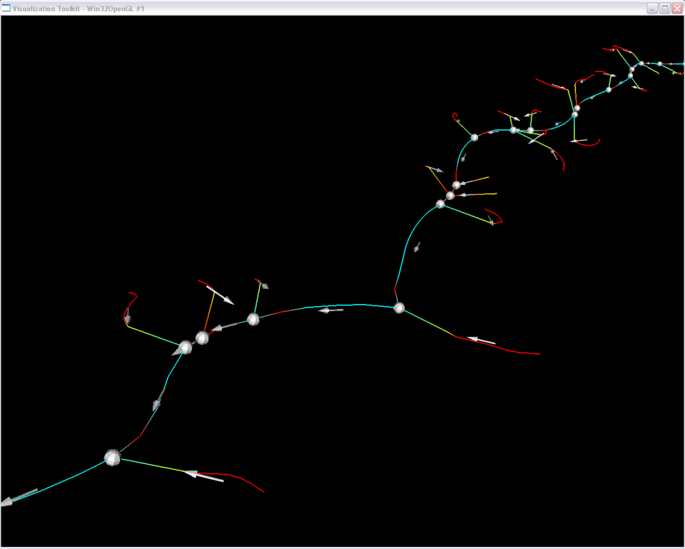
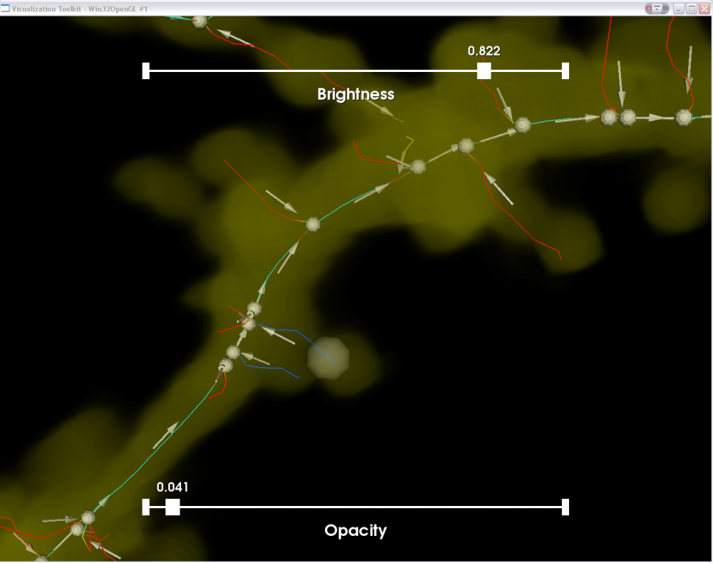
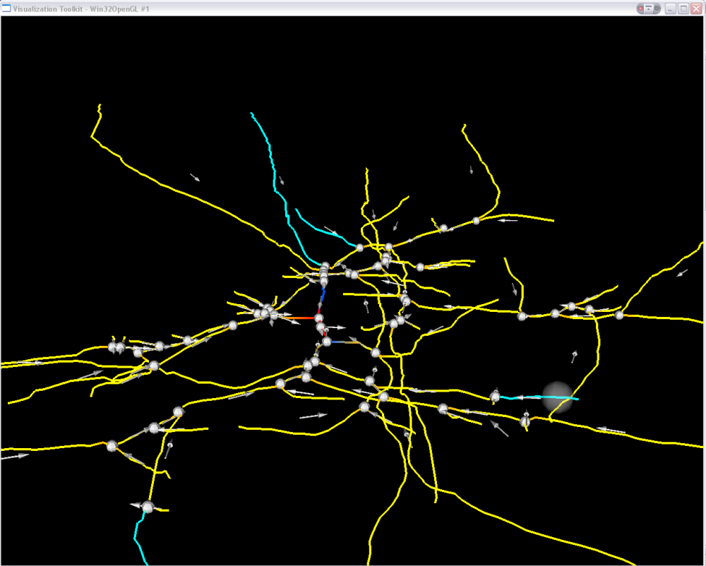
The FARSIGHT 3-D trace editor has a two-fold purpose: (i) to correct errors in automatic tracing of tube like structures such as neurites and vessel centerlines; and (ii) to record the trail of user edits from which the performance of the automated tracing algorithm can be assessed. To achieve these purposes, the trace editor displays the grayscale image as a volume rendering, over which the traces (supplied in one of the accepted file formats) are overlaid. The traces can be viewed in the context of the original data from any angle and at any desired magnification.
Since the traces are represented as a sequence of points in 3-D space, they have a sense (directionality). Many automatic tracing algorithms produce a collection of trace fragments (segments) that don't have a consistent set of directions (sense). The trace editor is designed to cope with this challenge. It is also designed to allow "group editing". You can select multiple segments at once, and perform an edit operation over the selected set of segments.
How to run the trace editor:
./trace_editor <input file(s)>
The Trace Editor will accept a string of input files, so both a trace file and a corresponding image file can be input at once. Currently Trace Editor accepts the following file types as input:
Trace Files:
  *swc ([Click here for details on this file format ])
  *xml (RPI format)
Image Files:
  *tks
  *tif
  *pic
For more information on the structure of the trace files see Common Tracing Output Format.
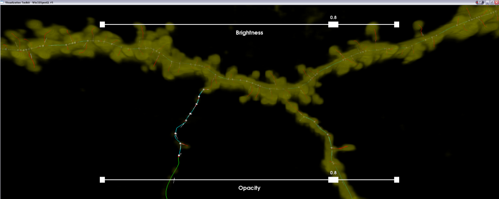
The results can show the Traces displayed as lines, and the original image as a 3D volume with adjustable brightness and opacity. This allows for validation of the traces, and a more intuitive way to visualization of the data than 2D slices or table formats.
In addition to being able to display the original image, the Trace Editor can also display segmented soma images. This data is also rendered in 3D and then overlaid on the traces. Rendering the somas along with the traces allows for more accurate validation. The increased accuracy enables greater ease in associating processes with the proper soma and also in correcting and validating the directionality of the processes.
Usage
Once the Trace Editor has successfully launched, the render window will have interactive 3-D viewing and editing capabilities. Several operations have automated and semi-automated functionality depending upon the input. For manual selective editing, you can point the computer mouse and highlight a series trace segments of by right clicking them(shown by selectable color). The editing operations are grouped by functions in the following categories of selection, modification, and settings.
- Selection operations, for controlling which traces are modified:
- Automatic Selection: Selects lines based on criteria, currently selecting only small lines and allowing deletion.
(Hot Key "A") - List Selection: Displays information about the currently selected trace lines.
(Hot Key "l") - Clear Selection: Deselect all currently highlighted lines. (Hot Key "c")
- (Hot key "-") removes the last selected line, color will revert to original when next pick is selected.
- Automatic Selection: Selects lines based on criteria, currently selecting only small lines and allowing deletion.
- Trace Modification Operations, for changing trace structure:
- Delete Trace: Removes all selected trace segments. (Hot Key "d")
- Split Trace: Split each selected trace line into two parts, separating them at the point that they were selected.
(Hot Key "s") - Merge Traces: operating in one of three modes it will attempt to merge traces based on selection inputs. The first time pressed it will determine and save all the comparisons for selection, and on second press will merge all selected comparisons.
(Hot Key "m")- Two Traces selected: If a merge is possible under the current tolerance it will be merged.
- Multiple Traces Selected: All probable merges will be made based on selected lines and current tolerance.
- Null Selection: If there are no currently selected lines all possible merges will be made from the entire trace structure.
- Flip Trace Direction: Flip the direction of the selected trace lines and update the rest of the tree consistently.
- Settings adjust global parameters:
- Tolerances: adjust the following rendering and threshold functions:
- Gap tolerance: the fraction of the length of the lines allowable for merging.
- Gap max: the maximum distance between endpoints allowed for merging.
- Small line: threshold for what is considered a fragment, or small line to be deleted.
- Selection color: Change the highlight color for selected lines.
- Line width: Adjustment for the width of rendered lines to help with visibility when displaying on screen.
- Apply edit settings
- Show Soma: If Loaded will display segmented soma.
- Tolerances: adjust the following rendering and threshold functions:
Complex Edit Operations
Note that the functions listed above are designed to handle multiple segments at a time. The MinEndPoints function determines the closest distances between trace endpoints, distances greater than the threshold are rejected. For detailed information on the features used in computation please see Trace Editor/Features. Conflicts between two lines attempting to connect to one endpoint are resolved by finding the closest endpoints. The merge command can be invoked on a set of traces, and this function will automatically connect all the possible segments. Multiple tracelines can be orginized and merged into a single linear trace.
With a series of selection and editing functions, groups related complex edits can be made at a single time. Split, Delete, and Merge when combined can preform advanced functions. Split can be uses to trim off the ends of traces, or when the trace turns in the wrong direction. Delete removes unwanted segments or fragments. Merge joins the segments into one line.
