TissueNets Program
Contents |
A Graph Builder for Secondary Associations
The complex brain tissues of interest to us contain a dense web of interesting relationships, so we use a graph-theoretic interpretation of associative measurements. An association can be described in terms of graphs in which each object is a node with a set of attributes (intrinsic measurements of the object), and each association is a link. Nodes and their attributes are uniquely identifiable by their object IDs. The attributes of each link is a list of measurements arising from associating the respective objects, and is uniquely identifiable by the ID’s of the associated objects. FARSIGHT includes a flexible facility for building and analyzing association graphs.
TissueNets program is mainly used for creating and displaying brain Tissue Networks. In addition, it is also possible to generate and display histograms based on the user's feature selections that are read from the input file. The program also provides users with sample input combination for demo purposes. TissueNets has the following menu selections:
Create Network
In general, the following steps are used for constructing a tissue network:
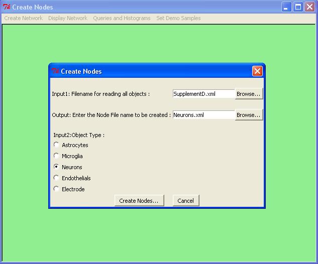
Step1: Define the Nodes
which creates nodes of the network. Below we show how to extract neurons from the input file SupplementD.xml:
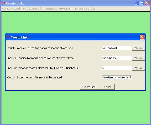
Step2: Define the Links
which creates links based on k-nearest neighbor algorithm (with exact solution). Here is how we can generate links for five nearest neighbors of every Neurons. The neighbors can only be Microglia.
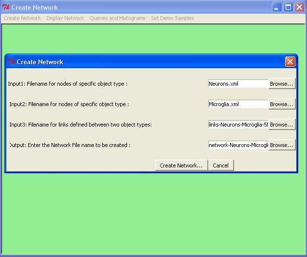
Step3: Form the Network
which combines nodes and links and creates a network in XGMML form. We now show how to form a network from the nodes and links we just constructed.
Display Network
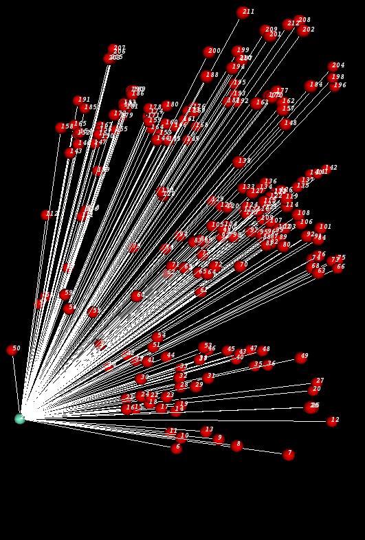
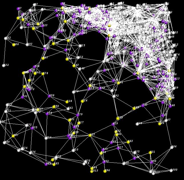
Once a network is created, TissueNets will help you to display it. After the network is displayed, the user can zoom and rotate the network to get a better view. Here is a sample network displayed by TissueNets:
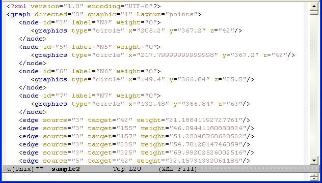
TissueNets displays networks in two different forms. The first one is just a standard network that consists of nodes and links (edges) defined in a network definition file (NDF) which is given as an input. The second type of networks is minimum-spanning trees that are generated from network definition files which are simply XGMML files. A node definition in an NDF is composed of node id, node label (whose first letter is descriptive, such as N for Neurons), and x, y, z coordinates. An edge can be constructed by specifying source and target nodes with the distance between them. A sample NDF is shown below:
TissueNets provides options to make proper selections. If the user wants to display a standard network, he/she can also display pyramidal regions by entering a cutoff point. When this option is selected, the average edge lengths that are used in pyramidal region computation will be produced in the file called pyramidal.txt. In addition, it is also possible to display links that are shorter than or equal to a given distance. In the following picture, the white cells are located outside the pyramidal region whose cutoff point is 50. In this case, yellow spheres represent microglia and purple ones are neurons.
USAGE:
If the user has mouse access:
  - scroll wheel zooms in and out
  - left mouse button is used for making selections
  - right mouse button is used for rotating the network
The user also can use the keyboard:
- key 'x' is used for rotating the network counter-clockwise by the x-axis (10 degrees each time).
Similarly SHIFT+'x' rotates clockwise by the x-axis.
- key 'y' is used for rotating the network counter-clockwise by the y-axis (10 degrees each time).
Similarly SHIFT+'y' rotates clockwise by the y-axis.
- key 'z' is used for rotating the network counter-clockwise by the z-axis (10 degrees each time).
Similarly SHIFT+'z' rotates clockwise by the z-axis.
- 'Delete' key deletes the selected vertices and edges
Queries and Histograms
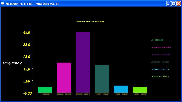
A set of features for specific cell types are presented here: [Features] These features are extracted from an input file and can be used to generate and display histograms (frequency vs feature). On completion, the histogram data and the image constructed will be saved automatically in the current directory. Here is a sample of an histogram:
Set Demo Samples
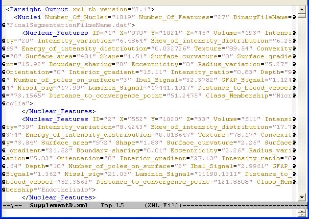
There are some predefined samples in TissueNets. When the user selects one of these samples, dialog boxes in each step will be filled out accordingly. Then the user can follow the other steps to create networks and display them. Note that in order to run the samples, the user still has to provide an input file that has features of all cells or electrodes. A sample input file with a proper format is shown below:
